25 Nov 2021
Explaining the limits of LiFePO4 batteries in parallel
If you have ever sought information about connecting Lithium Iron Phosphate (LiFePO4 or LFP) batteries in parallel for your application and been left confused by conflicting information, let me clear the buzz and explain why some sources allow us to connect LFP batteries in parallel and others do not recommend it at all.
First, we need to understand that when two or more batteries are connected in parallel, the current flowing through each battery is unlikely to be equal.
For example, imagine you have a battery system consisting of two 12V 100Ah batteries connected in parallel. If the system is under a 50A load, it is unlikely that each battery is experiencing an exact 25A load. One battery may experience 22A and the other 28A. The higher the load, the more significant the difference.
The unbalanced currents between batteries is caused by cell and battery manufacturing variations, differences in battery connection resistances and even site installation variables such as temperature differences between batteries.
The difference in current in each parallel branch causes the state of charge (SOC) of the batteries to diverge. The battery with the best ability to deliver power will deplete faster than the rest. The SOC of all batteries will converge again as the fastest depleting battery gets to a point where it can no longer deliver as much power to the system. At this point the stronger batteries will be those that initially delivered less power but are now at a higher SOC.
The upshot is that there will be differences in SOC in the batteries throughout most of the cycle life of the battery system. Differences in SOC between batteries means that even when the load is disconnected, there will be eddy current flowing between batteries as they equalise SOC. Eddy currents can be exceptionally high and cause batteries to go into an unpredictable protection mode.
It is important to note that the discharge curve of a LFP battery is very flat so it can take many hours for the batteries to equalise SOC once a load is removed. It is possible that the batteries won’t equalise no matter how long you wait due to diffusion voltages, or what some call ‘surface charge’.
It is how the battery management system (BMS) deals with the parallel branch current imbalances and the uncontrolled eddy currents that determine whether a manufacturer allows or does not allow parallel connections. The current in a parallel branch may be much higher than anticipated and will reduce the service life of the battery, or worse, exceed the battery capabilities.
A manufacturer may choose not to allow parallel connection because the parallel battery connection wiring and load is out of their control. As the uncontrolled currents have a negative effect on the service life of the battery, they will not warrant something they have no control over.
Other battery manufacturers may deal with the unknown connection wiring differences by allowing a maximum of two batteries in parallel and also stipulate that the maximum charge and discharge current is limited to the rating of one battery. This ensures that at no time is a single battery going to encounter loads greater than its maximum and this might reduce the risk of warranty claims due to a reduced service life. They may also stipulate that you must fully charge the batteries regularly to make sure the SOC of both batteries is brought back to an equal state.
Suppose a battery manufacturer has designed a smart BMS with tighter protection tolerances and a history function that allows fault and operation reporting. In that case, the manufacturer may allow more than two batteries to be placed in parallel. The reporting function allows the diagnosis of a battery system that might not be delivering the promised capacity. Parallel configurations with smarter BMS may still have rules that limit the maximum current allowed in the system but can allow more batteries to be wired in parallel.
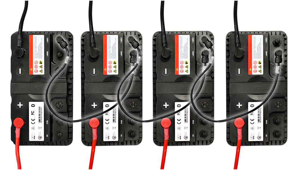
The most advanced and best option will be with a distributed BMS. In a distributed BMS all of the batteries are connected to a network. There will be a central control unit (CCU) or a battery that becomes the designated CCU, and there will be satellite batteries. The satellite batteries report their voltage, current, SOC and health plus other parameters onto the network. The CCU can sum and send control or warning information to the load or charger. The connected equipment might then reduce the current on the system before things get out of hand. The CCU can also command that all batteries go into protection mode.
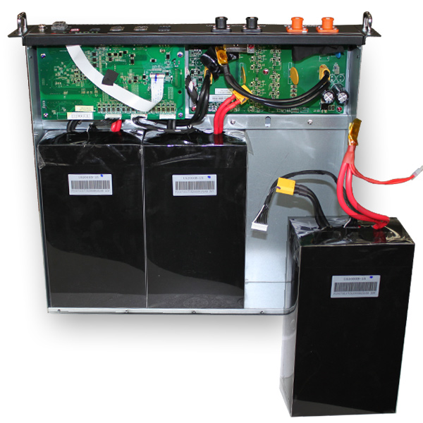
The advanced BMS controlled batteries with a CCU and satellites have more accurate safety margins and monitoring of parameters across the full battery system. They, therefore, enable the system to use more of the energy and power available and allow more batteries to be connected in parallel.

Differences in branch currents are always present due to variations in cells, battery assembly and installation wiring and location. How a BMS operates with parallel branch current imbalance determines battery parallel wiring capability. Since service life is negatively affected when current imbalances are experienced, there is also the question of whether the manufacturer warranty would be reduced.
All things considered, it is highly recommended you consult a battery expert to discuss your needs and get qualified advice on configuring suitable batteries for the application.
 |
Click here to download the PDF. |
Robert Hoehne