Arbin Battery Testers
LBTS-Cell
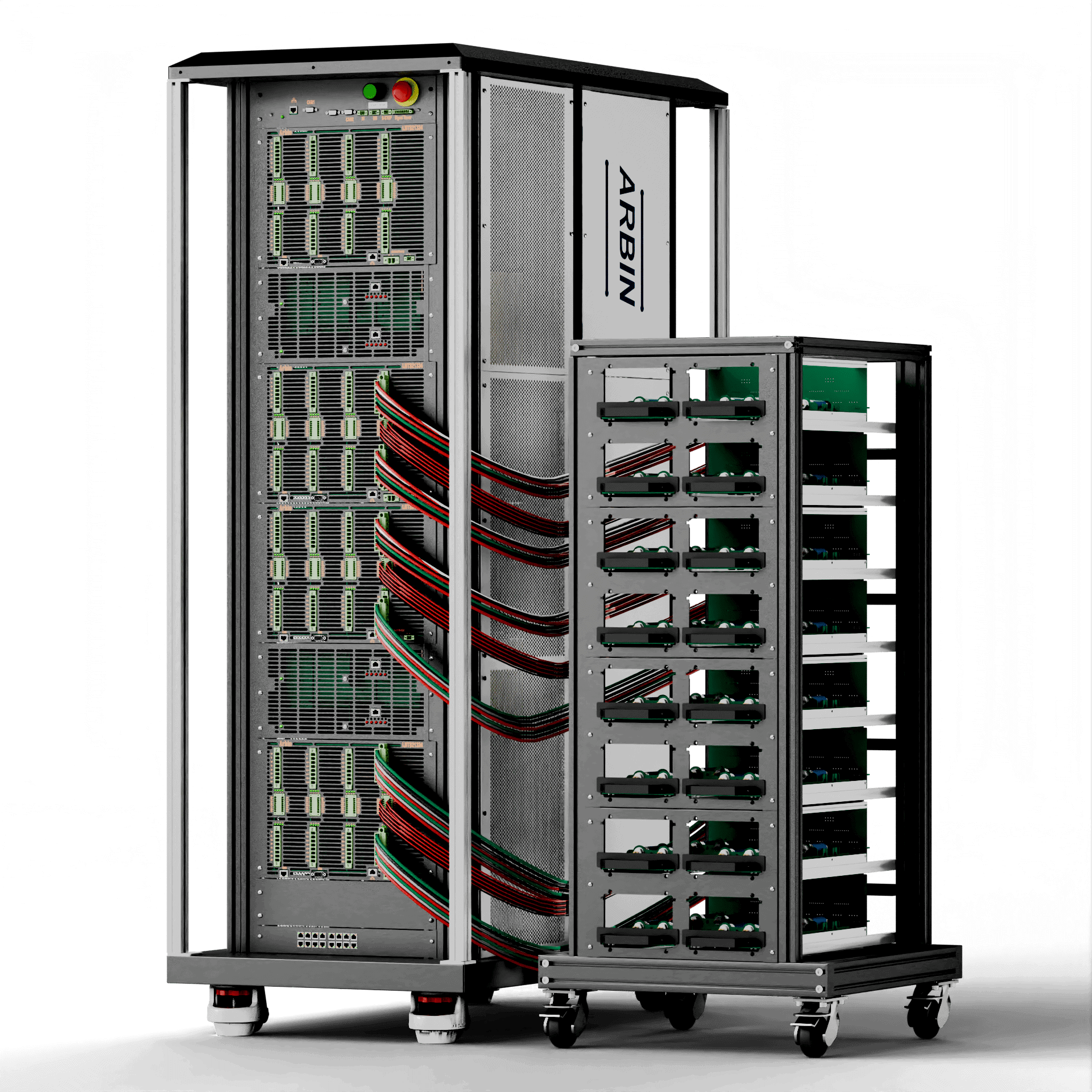
Arbin's LBTS Cell is essential for testing labs, offering advanced capabilities for various applications like cell quality control and battery development.
Highlights
- Ideal for battery development and cell characterization
- 4 Current Ranges per Channel
- <100ppm Measurement Precision
- 24-Bit Voltage & Current Measurement Resolution
- Built-in additional reference electrodes per channel available
- Built-in thermistor PT100 input per channel available
- Built-in DCIM Measurement feature
- Built-in Self Discharge Current Measurement feature
- Parallel channels up to 1200A
- EIS measurement up to 100kHz available
LBTS-Module
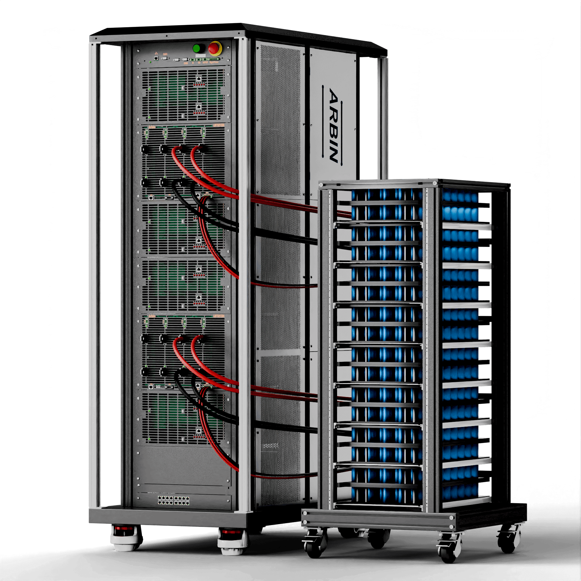
The LBTS-Module is equipped with Arbin's advanced technology, high precision, suitable for all purpose module testing.
Highlights
- Suitable for module R&D or End-of-Line applications.
- <100ppm Measurement Precision
- 24-Bit Measurement Resolution
- 20V, 30V, 40V, 60V, 80V, 100V configurations
- 4 Current Ranges per Channel
- Parallel any number of channels
System Specifications
| Number of Channels | 128 | 128 | 128 | 96 | 48 | 24 | 16 | 8 |
|---|---|---|---|---|---|---|---|---|
| Voltage Ranges | (-5V) - 5V | (-5V) - 5V | 0 - 5V | 0 - 5V | 0 - 5V | 0 - 5V | 0 - 5V | 0 - 5V |
| Current Ranges | 1A 100mA 10mA 1mA |
5A 100A 10mA 1mA |
10A 100A 10mA 1mA |
20A 100A 10mA 1mA |
50A 10A 1A 10mA |
100A 10A 1A 10mA |
150A 10A 1A 10mA |
300A 10A 1A 10mA |
| Measurement Resolution | 24bit | |||||||
| Measurement & Control Precision | +/-0.01% FSR | |||||||
| Measurement & Control Accuracy | +/-0.02% FSR | |||||||
| Input Impedance | 100G Ohm | |||||||
| Current Rise Time (10%-90%) |
<=200us | <=200us | <=200us | <=200us | <=1ms | <=1ms | <=1ms | <=2ms |
| Data Acquisition Rate | Regular mode: up to 1kHz, Burst Mode: up to 16kHz | |||||||
| Chassis Size (W x D x H) | 25"x45"x71" | |||||||
| Recommended Ambient Temperature | 0 ~ 30C | |||||||
| Input Voltage | 208V3P/380V3P/480V3P | |||||||
System Specifications
| Number of Channels | 24 | 12 | 24 | 12 | 32 | 16 | 32 | 16 | 32 | 16 | 16 |
|---|---|---|---|---|---|---|---|---|---|---|---|
| Voltage Ranges | 20V | 20V | 30V | 30V | 40V | 40V | 60V | 60V | 80V | 80V | 100V |
| Current Ranges | 40A 10A 1A 0.1mA |
80A 10A 1A 0.1A |
30A 10A 1A 0.1A |
60A 10A 1A 0.1A |
20A 5A 1A 0.1mA |
40A 10A 1A 0.1A |
12A 5A 1A 0.1A |
25A 10A 1A 0.1A |
10A 5A 1A 0.1mA |
20A 5A 1A 0.1A |
15A 5A 1A 0.1mA |
| Measurement Resolution | 24bit | ||||||||||
| Measurement & Control Precision | +/-0.01% FSR | ||||||||||
| Measurement & Control Accuracy | +/-0.02% FSR | ||||||||||
| Input Impedance | 4M Ohm | ||||||||||
| Current Rise Time (10%-90%) |
<=1ms | ||||||||||
| Data Acquisition Rate | Regular mode: up to 1kHz, Burst Mode: up to 16kHz | ||||||||||
| Chassis Size (W x D x H) | 25"x45"x71" | ||||||||||
| Recommended Ambient Temperature | 0 ~ 30C | ||||||||||
| Input Voltage | 208V3P/380V3P/480V3P | ||||||||||
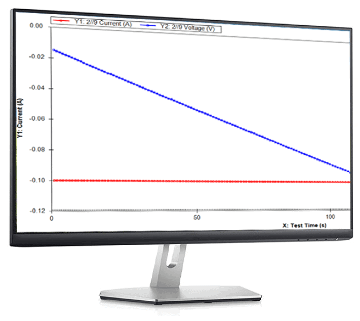
CC - Constant Current
The Constant Current (CC) control mode is designed to deliver a steady current to the battery based on the specified value. This mode is crucial in scenarios where maintaining a steady current is necessary, such as during charge or discharge cycles.
The polarity of the current determines the operation mode: a positive current corresponds to charging, while a negative current corresponds to discharging.
CV - Constant Voltage
The Constant Voltage (CV) control mode regulates the voltage output to the battery according to the set value. This mode is essential for applications where voltage stability is critical, ensuring the battery operates within safe voltage limits.
The CV mode is particularly useful in the latter stages of charging, where it ensures that the battery reaches and maintains the desired voltage level without exceeding it, thus protecting the battery's longevity and performance.
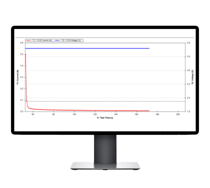
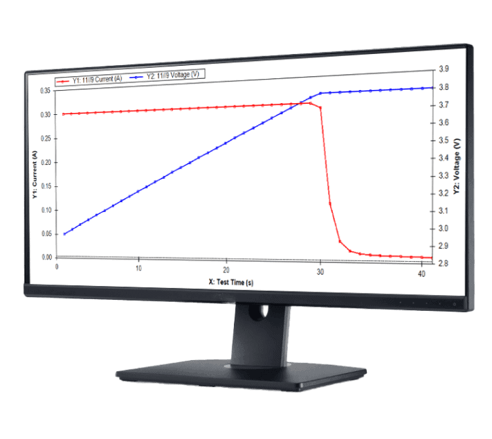
CCCV - Constant Current & Constant Voltage
The Constant Current-Constant Voltage (CCCV) control mode facilitates an integrated charging process, where the battery is initially charged under a Constant Current (CC) regime until a predefined voltage threshold is reached. Upon reaching this threshold, the system seamlessly transitions to a Constant Voltage (CV) mode, where the current gradually decreases as the battery approaches full charge.
You can specify both the current (CC) and voltage (CV) parameters in a single step. This mode ensures both efficient charging and the prevention of overcharging, with termination criteria based on either time or a minimum current threshold.